
Note: This guest post is by Lewis O’Leary, who has served as both a forensic investigator and restoration contractor since Hurricane Camille (1969). He has a degree in the fields of Mechanical Engineering and Architecture, is a “Building Envelope Consultant, Level 2, licensed by the Building Envelope Science Institute, a “HAAG Certified Inspector – Wind”, is a North Carolina Licensed Public Adjuster, and is a design/build, General Contractor licensed in North Carolina. Mr. O’Leary also serves as a consultant for engineering firms involved with wind damage from hurricanes and tornadoes. He can be contacted at 919-219-4099 or via e-mail at mailto:probuil@aol.com.
A manufacturer’s representative recently told a seasoned, commercial roofer that the old “12 inches on center” fastener spacing is still valid for their brand of TPO membranes. He did not set out any exceptions or limitations on his statement. I immediately challenged such a notion, promising that I would put something together to prove it.
When I Googled such, the following was posted:
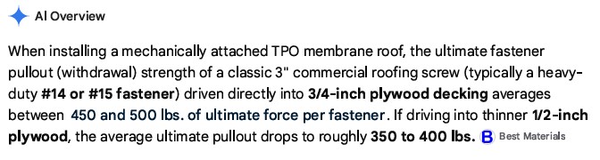
To avoid uplift failures during a severe storm like a hurricane, we add a “safety factor” of 2 to 3 to the design rating. The same Google discussion then set out the following. Specifically,

Converting from ¾” to ½”, this value goes down to 120 to 160 lbs. Using the 12” on center formula and 6’ between rows, this means that the “design load” rating would be at or around 140 lbs., which converts to an uplift for a 6 SF of roof area (the surface area that a single screw is holding down), which works out to 23.3 lbs. per SF, for ½” plywood.
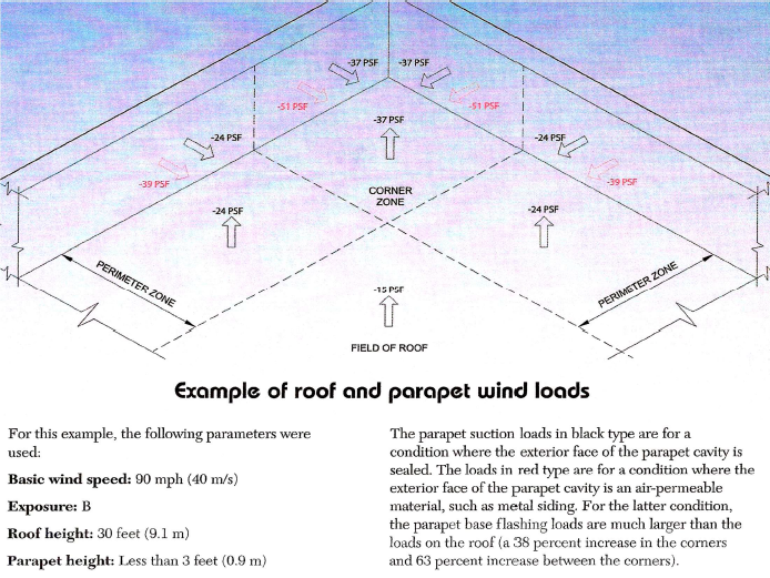
ASCE posted a graphical wind model in 2003 in Professional Roofing, entitled Detailing ASCE 7’s changes. The following page shows the model for wind loads, where the free-stream velocity was 90 mph. For the sake of this discussion, I am ignoring adjustments that might apply in other cases. The uplift values posted here are as follows:
-37 PSF in the corners
-24 PSF in the perimeter zone
-15 PSF in the field of the roof
Keep in mind that Force equals Mass times Velocity squared. If we adjust the 90-mph value up to 110 mph, these theoretical values will increase by about 50%.
This takes these same locations up as follows:
-55 PSF in the corners
-36 PSF in the perimeter zone
-22.5 PSF in the field of the roof
These values are still below the 350 to 400 PSF shown for the ultimate value for ½’ plywood, which equates to about 375 lbs. / 6 SF pr 62.5 lbs. per SF. However, this digs deeply into the safety factor for such a design, which, when you have a TPO system that is at or around 10 years old, can create “latent” damage that is not readily visible to the untrained eye.
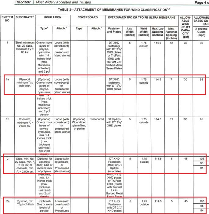
The same posting on Google goes on to elaborate on Fastener Spacing as follows:

The ESR 1597 Specification set out below sets the design rating for fasteners of this nature installed into various substrates. Note that the max fastener spacing is 5” & 7” for ½” plywood and 7” for mild steel. Also note that the maximum wind uplift ratings also go no higher than 105 mph for any of these 3 categories. Put another way, when you go from these recommended spacings to 12” on center, you are pushing well past the “design” limits.
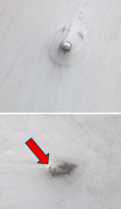 There is a middle ground between unaffected and absolute failure, concerning the uplift resistance of a screw that is exposed to wind lift well beyond its design limit. The two adjacent photos are examples of low level over stressing of fasteners in the open field of a TPO.
In each case, the 3” diameter circle is the outer ring of the washer for the screws. Experience tells me that the “pimple” in the middle of these rings is the fastener head itself, partially pulled out by at least 4 threads.
To determine just how much damage to the membrane has occurred thus far, I lightly dragged my tennis shoe over both of the fasteners shown here. This technique can expose any damage (micro-fractures) in the membrane directly over the fastener. As the tennis shoe drags across, it swipes away the dirt from the undamaged surface, leaving only the dirt that is in the micro-fractures.
Note that the membrane is beginning to tear at the edge of the fastener head (see red arrow).
As a TPO membrane gets older, the “plasticizers” that keep the material very flexible break down, causing the material to become somewhat brittle. As the fasteners begin to rise, they start overstressing the material directly above and around the edge of the fastener head. The net result is microfractures around the fastener head, which leads to tears like this (see red arrow). This membrane was believed to be around 9 years old.
The membrane here still has some amount of flexibility, which accounts for the fact that there were no more fractures than there are in these pictures.
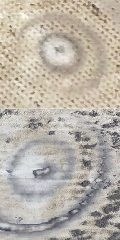 In the case of the fastener/washer assembly in the upper photo on the right, the “dirty” looking spot directly above the fastener head shows a larger area of dirt accumulation than the two fasteners above. However, the membrane here was reportedly around 13 years old. Using the same technique in the lower photo, a significant amount of the membrane directly above the fastener is fractured, resulting in a small area of the membrane being swept away also. This membrane was estimated to be over 15 years old.
In conclusion, when you have half of the current guidelines for fastener spacing, the “raised heads” can be spot repaired. However, it is important to remember that if one thread of a high-strength screw pulls through, the hole the screw sits in goes from being the ID of the threads to the OD. Essentially, the uplift resistance is reduced by over half because of the enlargement of the hole in the deck. Essentially, it is a reasonable conclusion that there are screws that have enlarged the hole in the deck by only a thread or two, then those that are 3 or 4 threads high. Experience tells me that you must pass the point where it has only risen 1 or 2 threads to get to 3 threads (the white circles), or to about 4 threads, where you can actually see an early-stage pimple.
Experience has shown that if you can find dozens of 4- or 5-threads-high fasteners, you can find considerably more cases where there are “white circles”, as shown in the photo below. When you have a fastener that is only 2 or 3 threads high, it can create a low “tent effect” with the inner rib. As it rains, it tends to wash off the dirt from this slightly higher area.
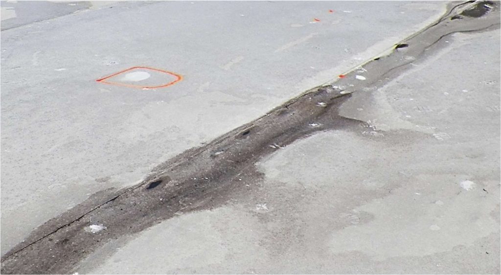
If the fastener rises slightly higher, the tent will reach out to the outer rib.
One might make a case that if you only have 50 “pimples”, that is a number that only qualifies for being a spot repair job using a larger screw. However, a compelling case can be made that this is a progressive problem. Simply put, if you can show that the number of small and large “white circles” is significantly higher than the number of pimples, the logical extension of this is that the number of fasteners that are only 1 or 2 threads high (not enough to create a white circle yet) will be significantly higher than the number of white circles. I have made such a case before, where a few dozen pimples turned out to be over 200 locations of high fasteners, ranging from slightly to significantly higher than allowed.
When you combine this with the inadequate spacing on the membrane, which requires doubling the number of fasteners to reduce the spacing to 6”, a reasonable case can be made that this is a constructive total loss. In an effort to establish that some or most of these were the result of a recent severe wind event, conducting an IR scan along with moisture meter readings can show that there was a relatively recent wind event that was strong enough to cause this type of damage.
 Credit is hereby afforded to GenFlex Roofing Systems for much of the insight I gained by becoming a certified installer in their TPO membrane roofing products.